Maintenance
This section outlines the maintenance procedures for the Proteus Safe System, which includes the robot, transport frame, Power and Control Center (PCC), and tools. The illustration below shows the main components of the Proteus Safe System:
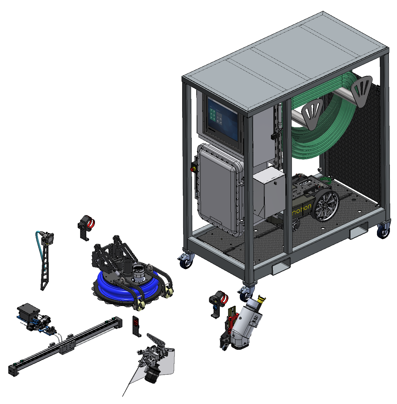
Figure – Proteus Safe System components illustrated view
Each component must be maintained regularly to ensure optimal performance and longevity. For detailed structural layouts and configurations of these parts, refer to the corresponding general arrangement drawings:
- 121097-GA-001 - Proteus Safe System - General arrangement drawing
- 122790-GA-001 - Transport Trolley - General arrangement drawing
- 117234-GA-001 - Proteus Safe Robot – General arrangement drawing
- 121421-GA-001 – Linear Tool – General arrangement drawing
- 119909-GA-001 – Sandblasting Tool – General arrangement drawing
- 122748-GA-001 – UHP Tool – General arrangement drawing
- 122623-GA-001 – Spray Painting Tool – General arrangement drawing
Always consult the latest version of the drawings for accurate system configurations before conducting any maintenance work on the robot, transport frame, PCC or tools.
- Daily maintenance checks
- Scheduled maintenance
- Pre-Operation checklist
- Post-Operation checklist
- Corrective maintenance
- Periodic Maintenance Schedule for Proteus Safe System