Screen frame
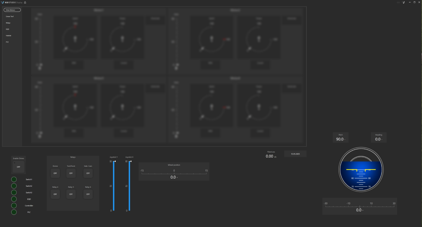
This frame is visible in all screens, enabling the operator to always have overview over XXX
Enable drivers (motors)
Cut the brakes and activate electrical motors.
- Switch1
Controls communications between the robot system and the operator. This function is more detailed in the Relays tab. - Switch2
Controls communications between the robot system and the operator. This function is more detailed in the Relays tab. - Switch3
Controls communications between the robot system and the operator. This function is more detailed in the Relays tab. - EQD
Status light for the Emergency Quick Release - Controller
Status light for the operator control - PLC
Status light for the programmable logic controller
Relays
- Dome
The overview Dome cameras is activated by this button. - Tool/front
Tooling camera and front camera are activated by this button - Hab. Cam
The Habitat tool camera is activated by this button. - Relay 4
N/A - Relay 5
N/A - Relay 6
N/A
- Joystick Y – 0-100
50 is zero position for the joystick in the given span - Joystick X – 0-100
50 is zero position for the joystick in the given span
Wheel position
The position of the wheels within the +/- 15 degrees span the robot can wheels can turn. If there is a discrepancy between the desired degree of turn and actual turn, the wheels may spin without finding purchase. Manually adjust the wheels to zero position if the problem continiues.
FibreLoss
This indicates if there is a loss of communication with the fibre connection.
Artificial Horizon
The Artificial Horizon on the right side of the screen is used to show how the robot is situated in relation to the ship hull.